
7.1 What is infrastructure?
Infrastructure is as important an area of the travel chain as the means of transport in terms of universal design. Infrastructure includes stations, terminals, stops and terminals, but also ICT.
Buildings related to public transport are regarded as work and public buildings in terms of universal design requirements. For buildings, requirements stipulated in the Planning and Building Act and the Building Technology Regulations (TEK 17) apply to universal design.
Requirements for universal design of buildings are regulated and specified in the Planning and Building Act, the Building Regulations (TEK 17) and its guidelines, as well as in various standards, in particular NS 11001-1:2018 Universal design of buildings – Part 1: Work and public buildings.
This chapter reproduces the most important requirements relating to universal design in public buildings, with reference to the Building Regulations, TEK 17. In addition, we review some relevant standards, user needs and recommendations.
7.2 Stations and terminals
7.2.1 Layout
Requirements in Regulations on technical requirements for construction works (Tek 17)
It is important to have good overall layouts for public buildings related to transport. It is important for passengers to be able to easily orient themselves to points you seek, from ticketing, toilets, cafeterias and platforms for trains and buses, without encountering barriers.
12-1. Requirements for layouts and universal design of buildings in Tek17 require that “Buildings for the public and work buildings shall be universally designed as follows from the provisions of the Regulations, unless the building or parts of the building are, in its function, unsuitable for persons with disabilities”.
A layout to meet universal design requirements should be simple and logical, with the use of right angles and colour emphasizing the layout. According to Section 12-5 of the Building Technology Regulations, buildings shall have a layout that makes it easy to find your way in them, and public buildings, such as train and bus terminals, shall have “layouts and distribution of rooms that ensure that as many people as possible have access to and can use all parts of the building that are open to the public”.
Guidelines and Norwegian standards
The Directorate for Building Quality’s guidelines to the Building Technology Regulations states that public buildings are “assessed in relation to planned and safe use, the possibility of good orientation, and the consideration of a good indoor environment”. Furthermore, “equal access to the rooms will mean that the main solution is usable for all the target groups for which the building is intended”[i]. All this must therefore be taken into account when developing a layout for public buildings related to transport. This includes:
- The needs of people with reduced mobility, orientation and sensitivity to substances in the environment should be dimensioning. In order for this to be achieved, the work must be based on some general principles for safeguarding these groups.
- The general principles include requirements and concrete norms for the design of the buildings related to the transport and principles of special types of facilities. One must base the work on general principles in order to safeguard the three dimensioning groups so that everyone can use the facilities; requirements, specific design norms, and principles for special types of facilities.
- The specific requirements will be measurable sizes that are stipulated, for example, in the Building Technology Regulations (Tek17) and standards (NS 11001-1 and more, these are not statutory) and include minimum requirements. It will be relevant to ensure that more passengers have access to the infrastructure that one considers choosing solutions that are better than the minimum requirements, for example when making choices that affect space, gradient, contrasting colors and more.
- Another consideration is the most recognizability in relation to different construction types; these should as much as possible be designed as identical as possible – for example, ticket counters, audience toilets, information points and the like. Recognizability reduces the risk of accidents, provides peace of mind, better flow and access to facilities and services.
- A design basis that includes passengers with disabilities, i.e. passengers with reduced mobility and power, visually impaired and hearing impaired, passengers with impaired speech and passengers sensitive to indoor climate factors, and others. If this is included in the design basis, the solutions will be good for all passengers.
- The main solutions should be designed so that they can be used by as many people as possible, in an equal way. The requirement covers both layouts and other factors that affect the usability of the edifice, such as lighting conditions, sound conditions and indoor environment. The further chapters describe this in detail.
7.2.2 Orientation and signage
Requirements in Regulations on technical requirements for construction works
In order to ensure equal access to information conveyed by signage, it shall be ensured that:
- Signs are placed in such a way that there is no risk of clashes.
- It should be possible to approach closely to the signs in order to read.
- The distance from the lower edge of the sign hanging from the ceiling or protruding from the wall is at least 2.25 m to the underlying floor.
- Signs and markings provide the necessary information.
- There should be visible luminance contrast of at least 0.8 between text and bottom color.
- Signs and markings are placed accessible and easily visible for both sitting and walking.
- Floor numbers are visually and tactilely readable on all floors, with luminance contrast 0.8.
- Signs and markings showing direction or space are designed and positioned so that it is easy to orientate.
- When changing the direction of walking, the direction information should be entered if necessary. Repetitive information should be as similar as possible throughout the building.
- Signs and markings are easily visible, logical and readable.
Recommendations
The Norwegian Blind Association has compiled an overview of the desired font size of signs in relation to reading distance to ensure the best possible readability:
“For signs that one can walk up to, smaller amounts of text should be designed with raised tactile letters. We also recommend braille.”
- For important signs, information should have tactile (elevated) font or symbol.
- Important information should be available on sound, possibly also in braille.
- Illuminated signs should have light text on a dark background to increase readability.
- Signs that can be walked all the way up to must have a letter height of at least 15 millimeters.
The table shows the minimum values for the font size of signs.
| Reading distance in meters | Versal (capital letters) in height in millimeters | Recommended sign height in millimeters |
| 1 – 3 | 30 | 60 |
| 3 | 50 | 100 |
| 5 | 75 | 150 |
| 10 | 120 | 240 |
Additional requirements for information boards:
• The information should be presented as sound and be subject to magnification.
- For display, use light writing on a dark background, minimum luminan contrast of 0.8.
Remember that the screen is a light source, a bright screen will therefore fade.” (Source: Norwegian Blind Association: Aesthetic, safe and accessible – A guide for the correct design of buildings. Oslo 2014)
7.2.3 Parking facilities
Requirements in Regulations on technical requirements for construction works
In connection with travel by bus and train, an important part of the travel chain is that passengers with disabilities should be able to park a car as close as possible to an entrance of a terminal building or other buildings that can be used by the public. This includes not only clear marking of the parking spaces and that they are located as close to the entrance as possible (maximum 25 meters according to the Directorate of Building Quality), but also that there is good lighting of the parking spaces, that it is easy to move to the main entrance and that there is access to installation space for example for electric wheelchairs, strollers, etc.
Section 8-9 of the Regulations on technical requirements for construction works requires that: “(3) Buildings with accommodation requiring lifts and buildings with a requirement for universal design shall have a sufficient number of parking spaces for disabled persons and sufficient other pitch for wheelchairs, strollers, etc.” [i].
- As part of a universally designed overall solution, buildings that require universal design and outdoor space for the general public must have a sufficient number of parking spaces for disabled people, in accordance with the Planning and Building Act. (See also 3.2.1).
- Parking spaces should be close to the main entrance.
- Parking space should have satisfactory lighting.
- The parking lot should be clearly signposted and marked.
- If parking meters are located near the parking lot, these must also comply with requirements for universal design of vending machines, see section 6.
Other relevant legislation
What is important is:
- 32.Universally designed payment solution, § 33. Exemption from payment for disabled persons, Chapter 10 Facilitation for disabled persons, including Section 61. Reservation of places for disabled persons with a parking permit, § 62. Assessment of sufficient number of places for people with disabilities, section 63. Size, design and placement of places, and section 64. Maximum time provisions.
From guidelines and Norwegian Standard
- The dimensions of a disabled parking lot[ii] are:
- Width 4.5 m and length 6.0 m (see Figure 7).
- When placing two parking spaces next to each other, manoeuvring area can be common to both cars.
The operating area may overlap the driving area provided the clear location of the parking space.
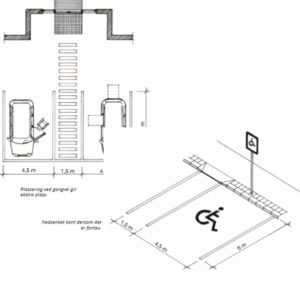
Figur 19: Dimensioning of parking space (NAD Norwegian Association of disabled)
7.2.4 Entrance
Requirements in Regulations on technical requirements for construction works
- It is important that the entrance to buildings related to bus and rail transport is located at the shortest possible distance from the parking lot and disembarkation point from, for example, taxi and bus, to ensure a universally designed solution. There are also several requirements for universal design of the entrance hall itself in accordance with TEK17.
- Walking access to buildings requiring universal design shall be step-free, have ascents not steeper than 1:15, except for stretches up to 5.0 m that may have ascents not steeper than 1:12; rest plane of at least 1.6 m x 1.6 m for every 1.0 m height difference; free width of mist 1.8 m; cross drops must max. 1:50; fixed and non-slip cover, visual and tactile demarcation and necessary lighting.
- The entrance hall should have lighting so that the entrance hall and main entrance door are visible in relation to surrounding surfaces.
- There should be a visual and tactile field of attention in front of the main entrance doors.
- Entrance halls should be step-free.
- Outside the main entrance doors there should be a horizontal field of at least 1.5 m x 1.5 m. If there is a side hinged door, the field should be located outside the impact radius of the door.
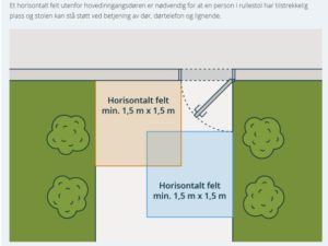
Figure 20 Outside main entrance doors there shall be a horizontal field of at least 1,5 m x 1,5 m (DIBK veiledning til Byggteknisk forskrift TEK17)
- Automatic door opener operation should be positioned so that it is accessible to people with wheelchairs and to avoid clashes with the door.
- The switch is positioned so that the person does not have to stay within the impact radius of the door while the switch is being operated. The purpose is to prevent the door from hitting the person when it opens.
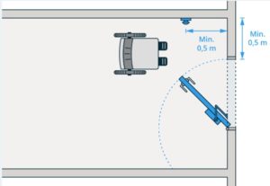
Figur 21: Service button for automatic door opener shall be placed is such a way that it is
accessible for persons in a wheelchair (Source: Direktoratet for byggkvalitet, veileder til TEK17)
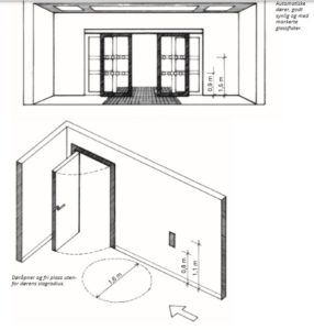
Figure 22: Dimensioning of entrance (Norwegian Association of Disabled (NAD))
7.2.5 Stairs and ramp
Requirements in the Regulations on technical requirements for construction works
Ramp
- In buildings requiring universal design, the beginning of the ramp must be marked in the entire width of the ramp with luminance contrast of at least 0.8 between marking and background.
Ramps should have handrails on both sides at one height with a height of more than 0.8 m above the deck, or at two heights with a height of 0.9 m and 0.7 m above the deck, respectively. The handrail should contrast with the wall and railing. The handrail should be designed to provide good grip.
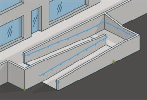
Figur 23: Example of ramp with one handrail (Source: Directorate for Building Quality, Guideline to TEK17)
- Ramp should have even and non-slip surface and a maximum rise of 1:15. For stretches below 3.0m, the rise can be a maximum of 1:12. For every 1.0 m height difference there should be a horizontal resting plane with a length of at least 1.5m.
- Ramp should have a width that is adapted to the expected transport, the minimum width should be 0.9 m.
Staircase
- Although stairs are a barrier for many passengers with disabilities, many other people with disabilities can use stairs. It is important that design requirements in accordance with the Building Regulations are complied with to ensure a universally designed solution.
- Stairs should have a secure demarcation and handrail on both sides. Handrails should be at one height with a height of more than 0.8 m, or at two heights with a height of 0.9 m and 0.7 m respectively, measured from the front edge of the stage.
- Steps should be marked to achieve luminance contrast of at least 0.8 relative to the step color. The marking on the stage should be in the entire width of the step at a maximum depth of 0.04 m.
- The staircase should have a steady climb and the same height at the height of the staircase. Entry into the walkline should be at least 0.25 m. Stairs with straight runs should have the same depth of entry.
- Landing shall have sufficient size to prevent and stop falls. Landings should be at least the same width as the stairwell. For straight stairs there should be at least 1.8 m. There should be landings at height differences of more than 3.3 m.
- Stairwells should have good lighting so that steps are visible. Steps should have a non-slip surface.
- Straight-run stairs must have a width of at least 0.90 m and a free height of at least 2.1 m.
- The main staircase with straight runs should have a width of at least 1.2 cm.
- The handrail must have luminance contrast of at least 0.8 compared to the background. At the beginning of each floor, the floor designation should be marked. The handrail should be routed at least 0.3m past the top and bottom stages with a rounded finish.
- The handrail must follow the stair run and around the middle landing (see figure)
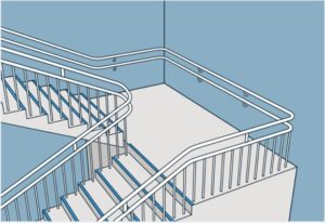
Figur 24: The handrail shall follow the stairway and round at the landing (Source: Directorate for Building Quality, Guideline for TEK17)
- There should be a danger warning field in front of the top staircase and an attention field in front of and up to the bottom step in the entire width of the staircase. The danger warning fielld and attention field should be marked tactilely and visually with luminance contrast of at least 0.8 in relation to the background. (see figure)
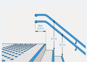
Figur 25: Either one handrail can be installed with upper edge 0,9 meter above the front edge of the instep and the other 0,2 meter lower, or one handrail can be installed in a height of 0,8 meter (Source: Directorate for building quality, Guideline for TEK17)
7.2.6 Elevator
Requirements in the Regulations on technical requirements for construction works
- It is a requirement to have installed a lift in public buildings and in work buildings with two floors or more.
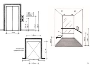
Figure 26: Dimensioning of lift (Norwegian Association of Disabled (NAD))
- Where a lift is required pursuant to section 12-3, the lift shall be adapted to persons with disabilities.
- The size of the lift chair must be dimensioned for presumed use.
- The free width of the doorway of an elevator should be at least 0.9 m.
- The surrounding walls should be sufficiently visible in relation to the elevator.
- In buildings with up to three floors and with little passenger traffic, lifting platform can replace lift. Lifts and lifting platforms shall be designed in accordance with the Elevator Directive and the Machinery Directive, respectively.
- The following size requirements apply:
- In buildings with three floors or more, at least one lift chair must have an internal size of at least 1.1 m x 2.1 m.
- In buildings with two floors, at least one lift chair must have an internal size of at least 1.1 m x 1.6 m.
- Lifting platforms should have an internal size of at least 1.1 m x 1.6 m.
7.2.7 Communication paths
Requirements in the Regulations on technical requirements for construction works
- Communication paths should be step-free, with ascents no steeper than 1:15.
- Corridors and galleries should have a free width of at least 1.5 m, in long corridors sufficient space should be allocated for two wheelchairs to pass each other. Stretches below 5.0 m where there is no door can have a free width of at least 1.2 m.
- Dazzling backlights should be avoided in communication paths.
- Columns and the like should be placed so that they do not obstruct communication paths. To avoid the risk of collision, columns and the like should have luminance contrast of at least 0.4 to the surroundings or be marked at two heights with luminance contrast of at least 0.8 to the background color.
- When changing the direction of walking, the direction information must be entered if necessary. Repetitive information should be as similar as possible throughout the building.
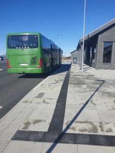
Figure 27 Examples of outdoor tactile guidelines with contrast for way-finding (Photo: Svein Ystanes, Kolumbus)
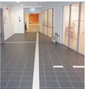
Figure 28: Examples of indoor guidelines with contrast for wayfinding (Photo: Ski Municipality and Jan Tore Lindskog/Omsorgsbygg Oslo KF)
- Large rooms, where central walkways run across open spaces, shall have a defined walking zone or necessary guideline. One should avoid using a pattern in floors that provides misleading directional information. The walking zone should have visual and tactile delimitation so that it is easily visible and palpable with a cane and feet (See also 4.7.2).
7.2.8 Information
Requirements in the Regulations on technical requirements for construction works
- In order for all passengers to have equal access to information, one must ensure that:
- Auditory information is supplemented with visual information. For example, information conveyed over speaker should also be readable on monitors.
- Information should be easy to read and perceive. Therefore, one should use as simple and clear language as possible when conveying information.
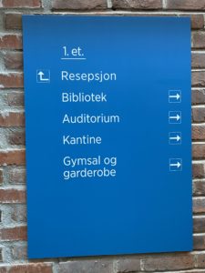
Figure 29: Sign with good contrast between text and background (Photo: Universell Utforming AS)
7.2.9 Administration/Reception
Requirements in the Regulations on technical requirements for construction works
- In buildings with a requirement for universal design, there must be a reception or information board where this is necessary. Receptions and information boards should be easy to find and centrally located in relation to the main access.
From Norwegian standard
- The counter must be able to be used by both standing and sitting persons. At least 1000 mm of the counter width should be height adapted to the sitting position (height 800 mm) for writing and operation.
- On each side of the counter there should be a maneuvering area for a circle with a diameter of at least 1600 mm.

Figur 30: Partially lowered counter (Photo: Universell Utforming AS)
7.2.10 Toilets
Requirements in the Regulations on technical requirements for construction works
To ensure a universally designed solution, the toilets must be usable for the function they should have. This includes:
- Size and layout shall be such that there is free floor space for wheelchair-accessible turning area in front of the toilet, at least 0.9 m free floor space on both sides of the toilet, which means that loose or fixed equipment cannot be placed here.
- There should be a clear area of at least 0.9 m up to the free space next to the toilet.
- The toilet should have hand rest on both sides, and hand rests mounted on the wall are recommended.
- Hand rests should have their own paper attachment, and it is recommended that they have cushioning when lowering so that they do not fall down and hit the person who wish to use the toilet.
- There should be sufficient free space under the washbasin, the minimum height between the floor and the lower edge wash of 0.67 m, at a depth of 0.5 m.
- Floors and walls should have visible contrast. Fixed equipment should have visible contrast to the floor and wall. Visible contrast means that the Luminance contrast must be a minimum of 0.4.
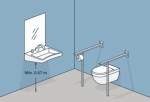
Figure 31: Visible contrast between the floor, walls and fixed equipment. (Source: Directorate for Building quality, TEK17 § 12-9 Figure 3)
- The turning area for wheelchairs should at least be a turning circle with a diameter of 1.5 m.
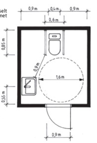
Figure 32: Bathroom and toilet – important details. The Norwegian Association of Disabled (NAD)
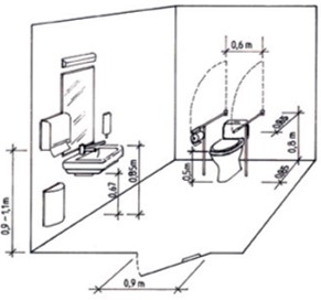
Figure 33: Bathroom and toilet – important details. The Norwegian Association of Disabled (NAD)
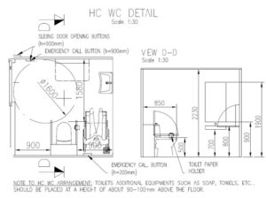
Figure 34: Example of placing of turning circle in front of toilet (Source: 4-All).
To ensure universal design, one must ensure that equipment and fixtures are placed in an appropriate manner. For example, trash cans must not be placed in toilet rooms in such a way that it poses obstacles, such as access to washbasin or paper dispenser.
7.2.11 Resting places
Requirements in the Regulations on technical requirements for construction works
- In terminals and similar areas with access for passengers there should be resting places.
7.2.12 Window and other glass panels
Requirements in the Regulations on technical requirements for construction works
- In buildings requiring universal design, windows and other glass panels in the outer wall above terrain must be secured.
- In the entrance hall and communication route, glass panes must be secured in the direction of traffic.
- Glass panels in the entrance hall and communication path where there may be a risk of collision should be contrasted with a glass marker, which is visible from both sides and at two heights, with centers 0.9 m and 1.5 m above the floor. The pattern in the glass marker in the door should be different from the glass marker in the nearby glass panel.
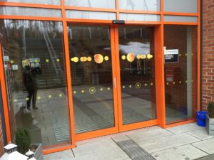
Figure 35: Different types of glass marking on glass panel and on door (Photo: Universell Utforming AS)
7.2.13 Lighting
Requirements in the Regulations on technical requirements for construction works
Lighting is central for passengers to be able to orient themselves and move without problems, not least in an emergency. There are good guidelines that can be consulted on lighting, including Lyskultur’s publication on light and universal design[i].
Obligatory requirements are:
- Buildings must have satisfactory access to light.
- Rooms for permanent residence shall have satisfactory access to daylight.
In order to achieve universal design, it is important that lighting is satisfactory for 1) evacuation and 2) that the public can carry out the tasks and receive the services that will take place in the building. It involves good planning of the lighting so that it helps to distinguish between floors and walls and ceilings and to illuminate, for example, signs, doors, stairs and other interior elements. To avoid glare, the light sources should be shielded and planned with respect to the users in the room.
The location of lighting in corridors and walking zones can emphasize the direction of this, making it easier to orientate.
Lighting should provide even light on the walkway. Point lighting that creates dark areas of the walkway must be avoided.
Stairs and the beginning of stairs should have good lighting. It is important that the lighting is positioned so that it does not dazzle people walking on the stairs, on their way up or down.
Signs must have sufficient lighting in order to be seen and read.
At counters and ticket gates, the lighting must be planned in respect of both customers and workers and in sufficient quantity to perform tasks related to this, for example, the use of payment machines or being able to read on the lips of the person serving the counter.
Guidelines and Norwegian standard
In accordance with Norwegian Standard NS 11001-1:2018, common areas shall have a lighting of at least 150 lx measured on floors. In addition, it will be important to have good planning and placement of lead lights for the purpose of evacuation, and that the lighting is planned in such a way that it contributes to a good understanding of space and room design.
[i] The Norwegian expert network Lyskultur has produced a publication on lighting and universal design in Norwegian language, see https://www.lyskultur.no/26-belysning-og-universell-utforming.6050512-342096.html
7.2.14 Acoustics
Requirements in the Regulations on technical requirements for construction works
- In buildings for the audience and work building there should be sound and voice transmission equipment, unless it can be documented that this is unnecessary to achieve good speech understanding. The entrance to rooms with amplified audio and voice transmission should be clearly marked.
In order to achieve universal design, it is important that sound and acoustics have an impact on orientation in and between rooms. This has to do with the use of materials, among other things, to reduce reverberation time and noise, and to facilitate good speech understanding.
Another important point is that sound should be clearly and evenly distributed, so good planning of acoustic conditions in the rooms and the use of speaker systems/sound distribution systems is therefore necessary. Sound equalization systems and loops shall be installed in rooms used by the general public, for example in foyers, terminals and warning systems.
7.3 Bus Stops
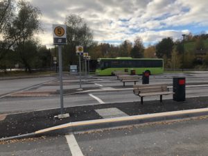
Figure 36 Bus stop with contrast stripe and bench (Photo: Viken county)
7.3.1 Introduction
Bus stops are an important part of the infrastructure around bus and rail transport. Universal design requirements include leader lines, tactile maps, any information desks, the boarding platforms themselves, any toilets, kiosks, storage boxes and more.
7.3.2 Statutory requirements
Requirements in the Regulations on technical requirements for construction works
- Walking access to outdoor living areas with a requirement for universal design shall a) be step-free, b) have ascents not steeper than 1:15, except for stretches up to 5.0 m that can have ascents not steeper than 1:12, c) have a rest schedule of at least 1.6 m x 1.6 m for every 1.0 m height difference, d) have free width minimum 1.8 m, except for stretches up to 5.0 m that can have a free width of minimum 1.4 m, e) have cross drops of maximum 1:50, f) have fixed and non-slip coverage, g) have visual and tactile delimitation.
- If several outdoor living areas have the same function, it is sufficient that at least one of these has walking access that meets the requirements of the first subsection litera b. Other walking admissions must have a maximum elevation of 1:10.
- Walkways shall be safe and dimensioned for expected traffic and transport.
- Central walkways that span open spaces in larger squares and squares that are to be universally designed shall have a clearly delimited walking zone or guideline. Patterns in the street grounds should not provide misleading directional information.
7.3.3 Guidelines and standards
Statens vegvesen Handbook N100 Road and street design
- Chapter D3 in the handbook provides requirements for universal design of stops (excerpts):
- Stops should be designed as edge stops or bus pockets (with or without traffic parts). For roads, there are requirements for stops given in each design class. In city streets and densely populated areas, stops can be designed as an edge stop or a bus pocket. Bus pocket should be installed at:• Speed limit 50 km/h at schools and institutions• Stops that have hub function where buses can have regulation time or long stay time• Lines with 30 buses or more in dimensioning hour
- Acceptable elevation at the stop depends, among other things, on the friction conditions that can be achieved by the chosen operating strategy for the stretch so that the bus is able to get started after stopping. Requirements for design of platform and waiting area:
- The platform should be at least 2.7 metres wide and should have a non-slip and smooth surface with level differences less than 2 cm.
- There should be a minimum of 2 m free passage on platform.
- Platform with centered public transport lane should have guide fences towards the lane and should be at least 3 m wide. In addition, there should be a safety distance of at least 0.4 m between installations in the platform (leskur and fences) and roads.
- There should be a resulting fall of at least 2% on the waiting area.
- Requirements for edge stone heights at stops are given in Chapter D.4.6.Stops and waiting areas are also described in handbook V123 Facilitation for collegiate transport on roads [15]. Design of guide lines and marking of breakpoints is shown in the manual V129 Universal design of roads and streets [19].
D 3.1 Location of stops
- Stops are recommended to be located after crossing. If the bus turns off on a secondary road, stops should be placed in the secondary road. Regarding planned intersections, bus stops along the main road should be avoided. Instead, the stops should be placed on the ramps near the secondary road so that the buses use the exit and exit ramps like other traffic. It should be ensured that the bus has visibility backwards in a length equal to the stop point when exiting from the stop. The stop should be positioned so that the bus has clearance of at least 5 m in front of a pedestrian area or at least 1 meter beyond a pedestrian area (the back of the bus).
Hand book V 123 Passenger transport handbook
Handbook V123 is part of the Norwegian Public Roads Administration’s handbook series and is a level 2 guide. The handbook must first and foremost be seen as a technical guide for planning and designing bus infrastructure. The guide is a supplement to the handbook N100 Road and Street Design which contains requirements related to the design of public transport facilities. Deviating from requirements in the normals follows established routines, cf. Handbook N100 Road and Street Design (see above). The handbook addresses, among other things, market and development features, physical sizes and dimensions, among other things, for buses, stops and turnarounds, public transport hubs and accessibility. The following are relevant statements:
7.3.4 Location of bus stop
Several factors must be considered when locating bus stops:
- contact with important destination points
- connection to pedestrian and cycle paths
- customer needs when placing pedestrian crossings so that pedestrians naturally use the designated crossing points whether they are in plan or level signs
- boarding
- assessment of road safety
- stops are placed according to signalling systems for the sake of bus priority
- platform should be on the right line for the sake of on and off both the front and rear doors. stops in the left curve are avoided as the driver has poor visibility and the right rear wheel difficult to reach the platform
- stops in the right curve are avoided as the driver and other traffic have poor visibility Holdes should not lie so that the bus stops closer than 5 m in front of a pedestrian lane or at least 1 m after the pedestrian area (the rear of the bus). Stops are laid where there is sufficient visibility in both directions, not in cluttered curves, at hilltops and the like. Stops can be placed within recreational zones at road junctions. The level of conflict will depend on bus frequency and traffic volumes. Reading sheds and bicycle parking are placed outside the recreational zone. Visibility should be secured backwards from the bus mirror in a length equal to 1.2 times the stop sight.
7.3.5 Choice of stop type
In the handbook N100 Road and street design there are different requirements for road and street both with regard to transport functions and modes of transport, environment, speed limits and traffic volumes. This has consequences for the choice and design of the stop type. The requirements are compiled in this chapter. When choosing a stop type, an assessment must always be made of road safety, accessibility and local conditions. The choice of stop type must also take into account the market and capacity needs.
Bus pocket is the area for stops adjacent to the carriageway. The stop can be in direct contact with the carriageway or separated from it by a refuge. Bus pockets provide good accessibility for car traffic, but normally lead to increased time spent on public transport. The entry and exit of the bus pocket takes longer than at edge stops and provides poorer comfort for passengers. Bus pocket also requires more area.
Edge stop is a stop with stops in the roadway. Edge stops prioritise public transport’s accessibility over car traffic. Edge stops provide short operating time, good comfort for bus passengers, are low area demanding, are easier to operate and maintain. Edge stops have lower investment costs than bus pockets. Where there is a lot of bus traffic, edge stops can hinder the accessibility of other buses and other traffic. In city streets and in densely populated areas, edge stops are recommended as the normal solution. Edge stops can also be established outside densely populated areas where, based on road safety considerations, it is acceptable for the bus to stop in the carriageway. Overtaking a bus at a stop at an edge stop can cause a traffic safety issue.
Dimensions of the platform:
- Length depends on bus type and number of simultaneous arrival buses.
- Width: Minimum 2.5 metres. V129
- Height:18 cm. In combination with low floor buses, this provides approximately stepless entry. V129
- Edge stone: Profile edge stone that makes it easier for the bus driver to manoeuvre the bus right up to the platform, increasing the quality in general and reducing/removing the need to use a ramp. V129
- Platform ramp up and down: 1:12. V129
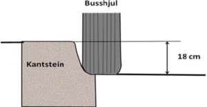
Figure 37 Drawing of bus wheel and rounded kerbstone
Read more at: https://www.vegvesen.no/_attachment/61485/binary/1010376?fast_title=H%C3%A5ndbok+V123+Kollektivh%C3%A5ndboka.pdf
Handbook V129 Universal Design of Roads and Streets
Handbook V129 is designed to contribute to the fulfilment of the National Transport Plan’s goal of a universally designed transport system and as part of the competence building in the agency.
The manual can also be freely used by counties and municipalities. The handbook is an aid in various processes and tasks in the Norwegian Public Roads Administration. The handbook will be revised and further developed as new knowledge and experiences are acquired. The manual addresses, among other things, the principles of universal design; universal design in planning, implementation and management, design basis; operation and maintenance; roads; streets; stops; means of transport; vending machines and ticketing. Chapter 8.1 states about stops:
Bus stop
This includes bus exit and exit points, the stop area and equipment/furniture related to this. These are discussed in Handbook V123 Facilitation of public transport on roads. Some elements are transferable to tram stops.
Recommended design
Design of the stop area:
- Straight entry (edge stop or pier)provides the best accessibility to all doors.
- The stop should be as visible as possible. This helps passengers find it and use the public transport service, and it helps to ensure that the driver sees the stop.
- When replanting, birch, worm, grass, spruce and burot should be avoided due to allergies.
- Grass should be mowed regularly
Dimensions of the platform
- Length depends on bus type and number of simultaneous arrival buses. See Manual N100 and Handbook V123.
- Width: Minimum 2.5 metres.
- Height:18 cm. In combination with low floor buses, this provides approximately stepless entry.
- Edge stone: Profile edge stone that makes it easier for the bus driver to manoeuvre the bus right up to the platform, increasing the quality in general and reducing/removing the need to use a ramp.
- Platform ramp up and down: 1:12.
Surface
The surface should be smooth and non-slip. The stop can be marked with deviant coatings against the rest of the pavement. This increases visibility in general, which is positive both for promoting public transport and for road safety and readability in the traffic picture. Edge stones should be smooth, non-dismissive and in contrast to surrounding surfaces.
Guide lines
Natural guide lines should lead to the bus stop ( edge stone, transition asphalt/grass etc). Prevent the bus stop area from extending backwards. If the stop is not located against a wall or a clear physical delimitation, a demarkation of the back edge with a fence or edge stone should be established. The following guide lines are designed with artificial guidelines to provide maximum information and recognizability:
- Bus stop marking: Attention area with width 90 cm and depth 30 cm when boarding at the front door.
- Guide line to stop: Attention area to the stop from the front part of the shelter or from the outer edge pavement and retaining plate, alternatively to the information bar if there is no shelter. The last 30 cm is laid as a field of attention – that is, the grooves are located crosswise.
See the handbook at Håndbok V129 Universell utforming av veger og gater (vegvesen.no)
Norwegian Standard
- Norwegian Standard NS 11001-1: Universal design of buildings – Part 1: Work and public buildings. This document deals with universal design of all types of work and public buildings and adjacent communal outdoor areas. Adjacent communal outdoor areas mean a made-up setting for parking and walking access. This document specifies the basis for meeting the requirements for universal design and equal use. This is specified by specifying design requirements, which will provide increased reliability and quality of use for everyone.
- Norwegian Standard NS 11005: Universal design of built-up outdoor areas – Requirements and recommendations. This standard sets requirements for universal design of built-up outdoor areas, thereby helping all people to have access to the area with opportunities for outdoor activities, outdoor activities, recreation, participation and socializing. The standard includes built-up outdoor areas in connection with buildings and facilities, green structure, nature and outdoor areas and transport facilities. The standard includes requirements for planning, execution and measures, elements and equipment. In order to achieve universal design, it is necessary that the connection between the different measures be emphasized and seen in a whole. Universal design is required throughout the life cycle of the measure both in planning and engineering and in the choice of solutions, products and workmanship, but the standard does not include requirements for jointing, operation and maintenance. The standard also contains recommendations that contribute to increased accessibility where universal design cannot be achieved.
7.3.6 Recommendations
- At a terminal, dynamic travel information (real-time on information screens showing departures and delays). Audio reading of text on the screen should also be possible.
- Information about timetables and route maps should be placed at a height that is also suitable for passengers in wheelchairs.
- Shelters with bench, ceiling light and contrast-marked (frosted) glass surfaces are installed.
- Benches should be equipped with backrests and armrests.
- Waste paper baskets are placed outside shelters, and in a way that they do not conflict with guide lines; 90 cm free passage on both sides of the guide line. Such garbage cans are equipped with contrast marking.
- Noise should prevented through signage and a ban on idling, or any other noise shielding.
- There should be bus stop markings in the road marking where e.g. bus should stop, so that tactile entry point is at the edge of the front door of the buses for safe boarding for passengers.
- It is recommended that there is a fence at the back of the boarding platform with contrast marking, this to prevent passengers from getting out into the carriageway of the buses.
- Kerb stones should be used as edge stone in the boarding and disembarkation areas of the platforms. This is to ensure that the bus driver can drive as close to the edge stones as possible to avoid a gap between the bus floor and the platitudes.
- A yellow contrast strip should be installed along the entire length of the platform for contrast marking.
- Height of edge stone should be 18 centimeters.
- There should be a maximum height of 20 mm on the difference between the elements of the platform, for example, surrendered ng between the pedestrian area and the bus platform. The facility shall as far as possible be accessible to wheelchairs.
- The gradient between the elements of the platform system should be 1:20.
- Lighting should be the best possible, for example, with the use of a light sensor and gradually stronger light according to how dark it is.’
7.3.7 Guidelines and user needs
From guidelines and standards
There are several standards and guidelines that are relevant for infrastructure. By standards, these are particularly relevant:
- Norwegian Standard NS 11001-1 Universal design of buildings – Part 1: Work and public buildings are relevant for infrastructure around trams and metros, such as larger stations, etc. This standard deals with universal design of all types of work and public buildings and adjacent communal outdoor areas. Adjacent communal outdoor areas mean a made-up setting for parking and walking access. This document specifies the basis for meeting the requirements for universal design and equal use. This is specified by specifying design requirements, which will provide increased reliability and quality of use for everyone.
- Norwegian Standard NS 11005 Universal design of built-up outdoor areas – Requirements and recommendations. This standard sets requirements for universal design of built-up outdoor areas, thereby helping all people to have access to the area with opportunities for outdoor activities, outdoor activities, recreation, participation and socializing. The standard includes built-up outdoor areas in connection with buildings and facilities, green structure, nature and outdoor areas and transport facilities. The standard includes requirements for planning, execution and measures, elements and equipment. In order to achieve universal design, it is necessary that the connection between the different measures be emphasized and seen in a whole. Universal design is required throughout the life cycle of the measure both in planning and engineering and in the choice of solutions, products and workmanship, but the standard does not include requirements for jointing, operation and maintenance. The standard also contains recommendations that contribute to increased accessibility where universal design cannot be achieved.
- Norwegian standard NS 8175 Sound conditions in buildings — Sound classes for different types of buildings, which record acoustics in, for example, terminal buildings, stations, etc.
- The Norwegian Public Roads Administration handbook universal design of roads and streets: https://www.vegvesen.no/_attachment/118984
- Bane Nor Station Manual: https://orv.banenor.no/stasjonshandboken/doku.php?id=start
User needs
While everyone has the same needs for a well-accessible travel chain, it is important to understand that different people face different barriers in connection with public transport travel. Some examples are:
- Orientation difficulties, such as knowing which bus, tram or other person arrives at the stop, find entrance doors on a means of transport.
- Finding your way in station buildings, terminals and other infrastructure.
- Lack of available information, including communication in audio format, signs with good luminan contrast and adapted letter height.
- Lack of defined walking zones and tactile leader lines.
- Lack of clear contrast markings on stairs, poles, lifts and protrusions.
7.4 Recommendations
- Information in connection with train journeys should be available in several formats, including visual and auditory format.
- Information should include availability of the train to be used, whether there is a need for the use of a ramp, whether there is space to move between rows of seats with a wheelchair, etc.
- Travel information should be in clear language and be received on multiple platforms, such as mobile application, website, etc. The use of symbols and icons is also recommended.
- Walkway to station should have the least possible height difference (max. 1:12 on short distances) and transition between pavements and pedestrian lanes no higher than 2.5 cm in height.
- For the visually impaired, it is important that there is a height difference between the walkway and the roadway so that you do not risk moving into the roadway.
- Maintenance of walkways by, among other things, sweeping snow and ice and a fixed and non-slip cover are also key measures, alongside requirements for visual and tactile demarcation and lighting[i].
- Train stations should have direct access without level differences.
- Seating, guide lines, stepless entry onto the train through sufficient height on edge stones and contrast use must be emphasized to ensure universal design.
- The train platform and station should have space for wheelchairs and be well maintained all year round.
- Ticket machines should have a operating height that allows use from a wheelchair; between 75 centimeters and 130 centimeters above the floor. The machine can then be used by both standing and sitting persons.
- Vending machines should be positioned so that they are easy to find, reach and operate, regardless of the time of day or light and weather conditions.
- The height of the machine can be adjustable, but must be within 75 and 130 centimeters above the floor. For example, you can mount the payment terminal on a telescopic pole, which the user can adjust to their liking.
- Train carriages should be low floor/low entry with a ramp that ensures stepless on and disembarkation for all passengers to the train carriages.
- Proper use of contrasting colors and allocated spaces for wheelchairs and guide dogs is important.